
| decimal numbers: | ||
| exponential numbers: |
It is assumed that the gas can be considered to be an ideal gas and that the calorically perfect gas assumption applies.
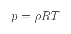
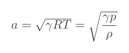
With the assumptions above, speed of sound is a function of temperature and gas properties
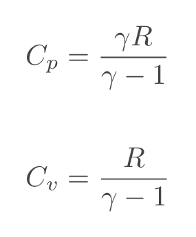
Specific heat at constant pressure, \(C_p\), and specific heat at constant temperature, \(C_v\), are calculated from the specified gas data according to:
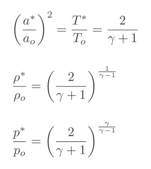
The sonic conditions (starred quantities) are the flow conditions that we would get if we could slow down or accelerate the fluid to sonic speed adiabatically (without adding or removing heat). If the sonic conditions are normalized suing the corresponding total/stagnation properties (the flow conditions we would get if we could slow the fluid down to zero velocity isentropically), it becomes a constant for a specific gas.
More details can be found here:
| introduction to compressible flow | (Gas properties, Isentropic relations) |
| One-dimensional flow | (Total and critical conditions & Alternative forms of the energy equation) |
Update gas data if needed. The default values are \(\gamma=1.4\) and \(R=287\), which corresponds to air. Changing the gas properties will affect all sections of the CFLOW calculator.
| ratio of specific heats \(\left(\gamma=C_p/C_v\right)\): | ||||
| gas constant \(\left(R\right)\): |
Specify two of the varibales pressure, temperature, and density and calculate the third variable using the ideal gas law.
| select mode | ||||||
| temperature \(\left(T\right)\) | ||||||
| density \(\left(\rho\right)\) | ||||||
| pressure \(\left(p\right)\) | ||||||
Specify fluid temperature or fluid pressure and density and calculate the corresponding speed of sound assuming calorically perfect gas.
| select mode | ||||||
| temperature \(\left(T\right)\) | ||||||
| density \(\left(\rho\right)\) | ||||||
| pressure \(\left(p\right)\) | ||||||
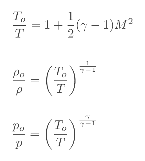
Total flow conditions or stagnation flow conditions are the flow conditions that we would get if we could slow the fluid down to zero velocity isentropically i.e., without heat exchange or introduction of losses. In an adiabatic flow, total temperature and total speed of sound are constants and in an isentropic flow all total properties are constants. The ratios of static and total flow properties can be obtained using the following relations
More details can be found here:
| One-dimensional flow | (Total and critical conditions & Alternative forms of the energy equation) |
Update gas data if needed. The default values are \(\gamma=1.4\) and \(R=287\), which corresponds to air. Changing the gas properties will affect all sections of the CFLOW calculator.
| ratio of specific heats \(\left(\gamma=C_p/C_v\right)\): | ||||
| gas constant \(\left(R\right)\): |
Calculate ratios of static and total flow properties based on the specified input.
| Select problem type | ||||||
| Mach number \(\left(M\right)\) | ||||||
| temperature ratio \(\left(T_o/T\right)\) | ||||||
| pressure ratio \(\left(p_o/p\right)\) | ||||||
| desnity ratio \(\left(\rho_o/\rho\right)\) | ||||||
Convert static flow properties to total or the other way around.
| Mode: | ||||||
| Mach number: | ||||||
| Pressure: | ||||||
| Temperature: |
A normal shock is a discontinuity in flow quantities. The change of quantities is an adiabatic process (no heat is added), which means that total temperature will be constant over the shock. All other flow properties will change. Upstream of the shock, the flow must be supersonic (M > 1.0) and downstream of the shock, the flow is subsonic (M < 1.0). Over the normal shock, flow quantities will change as follows:
| flow property | change over normal shock |
|---|---|
| density | increases |
| pressure | increases |
| velocity | decreases |
| Mach number | decreases (from M>1 to M<1) |
| temperature | increases |
| total pressure | decreases |
| entropy | increases |
| total temperature | unaffected |
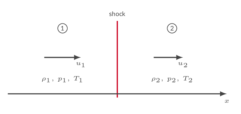
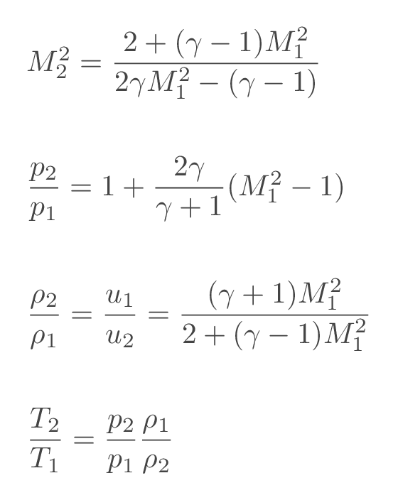
A typical problem is the two-station problem i.e., a problem where flow properties are known upstream of the normal shock and the downstream flow properties should be calculated or the other way around. This is done using the normal shock relations.
More details can be found here:
| One-dimensional flow | (Normal-shock relations) |
Update gas data if needed. The default values are \(\gamma=1.4\) and \(R=287\), which corresponds to air. Changing the gas properties will affect all sections of the CFLOW calculator.
| ratio of specific heats \(\left(\gamma=C_p/C_v\right)\): | ||||
| gas constant \(\left(R\right)\): |
Ratios of downstream and upstream flow properties are calculated based on specified input.
| Select problem type | ||||||
| upstream Mach number \(\left(M_1\right)\) | ||||||
| downstream Mach number \(\left(M_2\right)\) | ||||||
| temperature ratio \(\left(T_2/T_1\right)\) | ||||||
| pressure ratio \(\left(p_2/p_1\right)\) | ||||||
| density ratio \(\left(\rho_2/\rho_1\right)\) | ||||||
| total pressure ratio \(\left(p_{o_2}/p_{o_1}\right)\) | ||||||
Two-station problem: specify flow conditions upstream of the normal shock and press recalculate to get the flow conditions downstream of the shock.
| Mach number \(\left(M_1\right)\): | ||||||
| pressure \(\left(p_1\right)\): | ||||||
| temperature \(\left(T_1\right)\): |
When heat is added to a one-dimensional flow, the Mach number will approach 1.0 (sonic flow). For an initially subsonic flow, the Mach number will increase until sonic conditions are reached and for an initially supersonic flow, added heat will reduce the Mach number until sonic conditions are reached. The heat addition for which sonic conditions are reached is denoted \(q^*\) and starred flow properties are flow properties at sonic conditions. The starred flow quantities are constants in a specific flow. When sonic conditions are reached, the flow is choked, and more heat cannot be added without changing the upstream flow conditions.
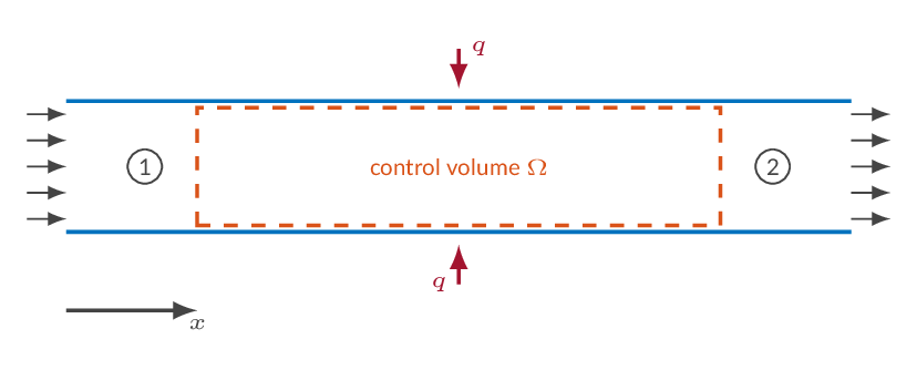
A typical problem is the two-station problem i.e., a problem where flow properties are known at one location in the flow and the flow properties in an upstream or downstream location should be calculated. This is done using the starred quantities as a reference state. The starred flow quantities are calculated based on the flow quantities in station 1. As the starred quantities are constants, they can be used together with the added heat to calculate the flow properties in station 2.
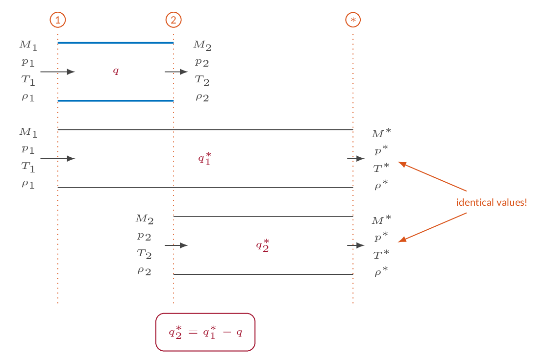
| flow property | adding heat to a subsonic flow | adding heat to a supersonic flow |
|---|---|---|
| density | decreases | increases |
| pressure | decreases | increases |
| velocity | increases | decreases |
| Mach number | increases | decreases |
| total pressure | decreases | decreases |
| entropy | increases | increases |
| total temperature | increases | increases |
More details can be found here:
| One-dimensional flow | (One-dimensional flow with heat addition) |
Update gas data if needed. The default values are \(\gamma=1.4\) and \(R=287\), which corresponds to air. Changing the gas properties will affect all sections of the CFLOW calculator.
| ratio of specific heats \(\left(\gamma=C_p/C_v\right)\): | ||||
| gas constant \(\left(R\right)\): |
The ratio of flow quantities and corresponding starred flow quantities (flow quantities at sonic conditions) are calculated based on specified input.
| Select problem type | ||||||
| Mach number \(\left(M\right)\) | ||||||
| temperature ratio (subsonic) \(\left(T/T^*\right)\) | ||||||
| temperature ratio (supersonic) \(\left(T/T^*\right)\) | ||||||
| pressure ratio \(\left(p/p^*\right)\) | ||||||
| temperature ratio (subsonic) \(\left(T_o/T_o^*\right)\) | ||||||
| temperature ratio (supersonic) \(\left(T_o/T_o^*\right)\) | ||||||
Specify flow conditions at one location and calculate corresponding flow properties at an upstream or downstream location. The second station is defined by specifying added heat, Mach number, pressure, or temperature. The added-heat-budget figure shows the added heat in relation to the maximum allowed heat addition \(q^*\) and the Rayleigh curve shows the two flow stations in relation to the sonic flow condition.
| pipe diameter \(\left(D\right)\): | ||||
| pipe length \(\left(L\right)\): |
| Mach number \(\left(M_1\right)\): | ||||||
| pressure \(\left(p_1\right)\): | ||||||
| temperature \(\left(T_1\right)\): |
| select problem type | ||||||
| added heat \(\left(q_{1-2}\right)\): | ||||||
| Mach number \(\left(M_2\right)\): | ||||||
| pressure \(\left(p_2\right)\): | ||||||
| temperature \(\left(T_2\right)\): | ||||||
| added heat \(\left(\%\ \text{of}\ q^\ast\right)\): | ||||||
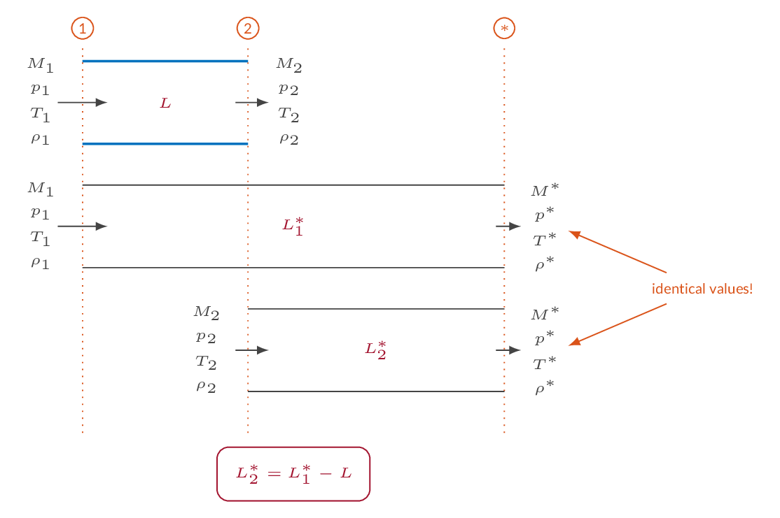
When friction is added to a one-dimensional flow, the Mach number will approach 1.0 (sonic flow). For an initially subsonic flow, the Mach number will increase until sonic conditions are reached and for an initially supersonic flow, added friction will reduce the Mach number until sonic conditions are reached. In the calculations below, friction is introduced using a constant friction factor, which means that the amount of friction added is a linear function of pipe length. The length for which sonic conditions are reached is denoted \(L^*\) and starred flow properties are flow properties at sonic conditions. The starred flow quantities are constants in a specific flow. When sonic conditions are reached, the flow is choked and more friction (pipe length) cannot be added without changing the upstream flow conditions.
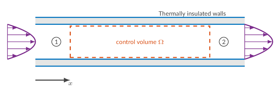
A typical problem is the two-station problem i.e., a problem where flow properties are known at one location in the flow and the flow properties in an upstream or downstream location should be calculated. This is done using the starred quantities as a reference state. The starred flow quantities are calculated based on the flow quantities in station 1. As the starred quantities are constants, they can be used together with the added friction to calculate the flow properties in station 2.
| flow property | subsonic flow with friction | supersonic flow with friction |
|---|---|---|
| density | decreases | increases |
| pressure | decreases | increases |
| temperature | decreases | increases |
| velocity | increases | decreases |
| Mach number | increases | decreases |
| total pressure | decreases | decreases |
| entropy | increases | increases |
More details can be found here:
| One-dimensional flow | (One-dimensional flow with friction) |
Update gas data if needed. The default values are \(\gamma=1.4\) and \(R=287\), which corresponds to air. Changing the gas properties will affect all sections of the CFLOW calculator.
| ratio of specific heats \(\left(\gamma=C_p/C_v\right)\): | ||||
| gas constant \(\left(R\right)\): |
The ratio of flow quantities and corresponding starred flow quantities (flow quantities at sonic conditions) are calculated based on specified input.
| Select problem type | ||||||
| Mach number \(\left(M\right)\) | ||||||
| temperature ratio \(\left(T/T^*\right)\) | ||||||
| pressure ratio (subsonic) \(\left(p/p^*\right)\) | ||||||
| pressure ratio (supersonic) \(\left(p/p^*\right)\) | ||||||
| \(4\bar{f}L^*/D\) (subsonic) | ||||||
| \(4\bar{f}L^*/D\) (supersonic) | ||||||
Specify flow conditions at one location and calculate corresponding flow properties at an upstream or downstream location. The second station is defined by setting position (length), Mach number, pressure, or temperature. The pipe-length-budget figure shows the pipe length in relation to the maximum allowed length \(L^*\) and the Fanno curve shows the two flow stations in relation to the sonic flow condition.
| pipe diameter \(\left(D\right)\): | ||||
| friction coefficient \(\left(\bar{f}\right)\): |
| axial coordinate \(\left(L_1\right)\): | ||||||
| Mach number \(\left(M_1\right)\): | ||||||
| pressure \(\left(p_1\right)\): | ||||||
| temperature \(\left(T_1\right)\): |
| select problem type | ||||||
| axial coordinate \(\left(L_2\right)\): | ||||||
| Mach number \(\left(M_2\right)\): | ||||||
| pressure \(\left(p_2\right)\): | ||||||
| temperature \(\left(T_2\right)\): | ||||||
| tube length \(\left(L_{12}\right)\): | ||||||
| pipe length \(\left(\%\ \text{of}\ L^\ast\right)\): | ||||||
An oblique shock is a shock with an angle to the flow direction. The oblique shock relations are in principle the same as those for normal if the upstream and downstream Mach numbers are replaced with Mach numbers in the shock-normal direction. An oblique shock may appear in a supersonic flow when there is a need for a change of flow direction as in the compression corner example below. The sharp compression corner will lead to the generation of an oblique shock starting at the corner (left figure) while a gradual compression (right figure) will result in a compression region that eventually coalesces into an oblique shock.
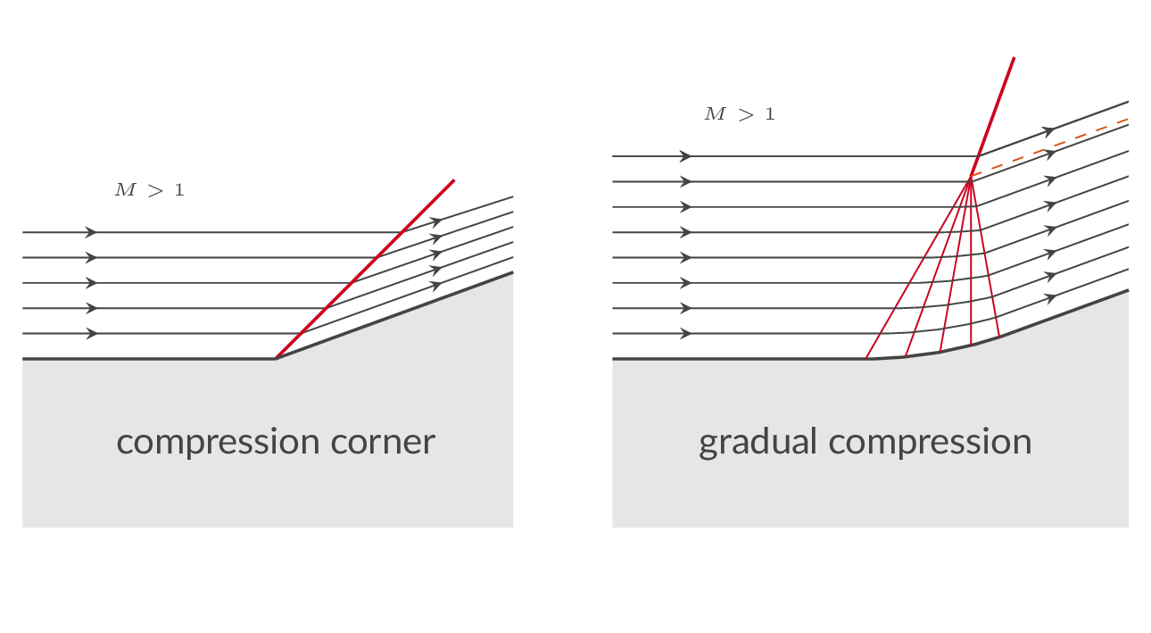
The angles involved in the oblique shock analysis are given in the figure below. \(\beta\) is the shock angle (angle related to the flow direction upstream of the shock), \(\theta\) is the flow deflection angle (turning of the flow as it goes through the shock).
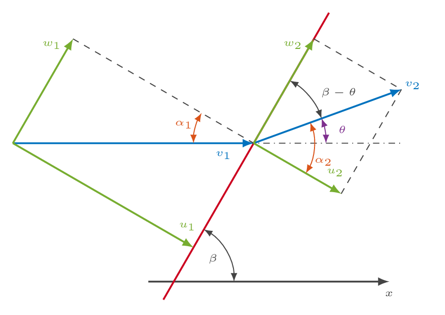
The relation between the deflection angle \(\theta\), the shock angle \(\beta\) and the upstream Mach number \(M_1\) is called the \(\theta\)-\(\beta\)-Mach relation and is given by

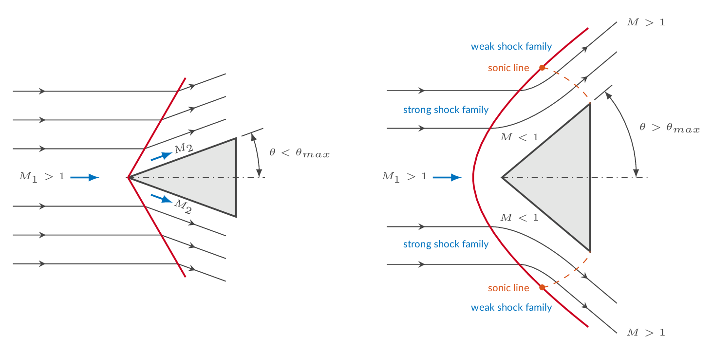
For each Mach number there is a maximum possible flow deflection angle i.e., the flow cannot be turned more than this maximum deflection angle unless the Mach number is increased. If the flow needs to deflect more than the maximum deflection angle, a detached shock will be formed in front of the location where the flow angle needs to change. The figure below shows the flow over a wedge. In the eft figure the deflection angle is within the possible range and thus an oblique shock will form at the leading edge of the wedge. If the deflection angle is greater than the maximum deflection angle (right figure) a detached shock is formed in front of the object. At the centerline the detached shock is normal to the flow direction (a normal shock). The normal shock evolves into a strong oblique shock (an oblique shock with a subsonic flow downstream) and even further out the oblique shock will be of the weak shock family (supersonic flow downstream).
| flow property | change over oblique shock |
|---|---|
| density | increases |
| pressure | increases |
| temperature | increases |
| velocity | decreases |
| Mach number | decreases |
More details can be found here:
| Oblique shocks and expansion waves | (Oblique shock relations) |
Update gas data if needed. The default values are \(\gamma=1.4\) and \(R=287\), which corresponds to air. Changing the gas properties will affect all sections of the CFLOW calculator.
| ratio of specific heats \(\left(\gamma=C_p/C_v\right)\): | ||||
| gas constant \(\left(R\right)\): |
Problem type 1: The upstream flow conditions and the deflection angle are known. Update upstream Mach number, flow deflection angle, upstream pressure and temperature. Press the recalculate button to calculate shock angle and downstream flow conditions. The three figures below shows solutions (weak and strong) in the form of a \(\theta\)-\(\beta\)-Mach plot, a shock polar and a pressure deflection diagram.
| upstream Mach number \(\left(M_1\right)\) | ||||||
| deflection angle \(\left(\theta\right)\) | ||||||
| upstream pressure \(\left(p_1\right)\) | ||||||
| upstream temperature \(\left(T_1\right)\) |
Problem type 2: The upstream flow conditions and the shock angle are known. Update upstream Mach number, shock angle, upstream pressure and temperature. Press the recalculate button to calculate the flow deflection angle and downstream flow conditions. The three figures below shows solution in the form of a \(\theta\)-\(\beta\)-Mach plot, a shock polar and a pressure deflection diagram.
| Mach number \(\left(M_1\right)\) | ||||||
| shock angle \(\left(\beta\right)\) | ||||||
| upstream pressure \(\left(p_1\right)\) | ||||||
| upstream temperature \(\left(T_1\right)\) |
An expansion region or expansion fan is generated in a supersonic flow when the flow direction needs to change such that the flow area increases - the flow turns out from itself. The expansion region constitutes a collection of an infinite number of Mach waves. Each Mach wave contributes with an infinitesimal change in flow direction and flow properties without introduction of losses i.e., the process is isentropic. Thus, the integrated effect over the expansion region is also isentropic. In the figure below, the sharp expansion corner (left figure) will lead to the generation of a centered simple wave or expansion fan and the gradual expansion (right figure) will generate a simple wave (that might be centered depending on the shape of the wall)
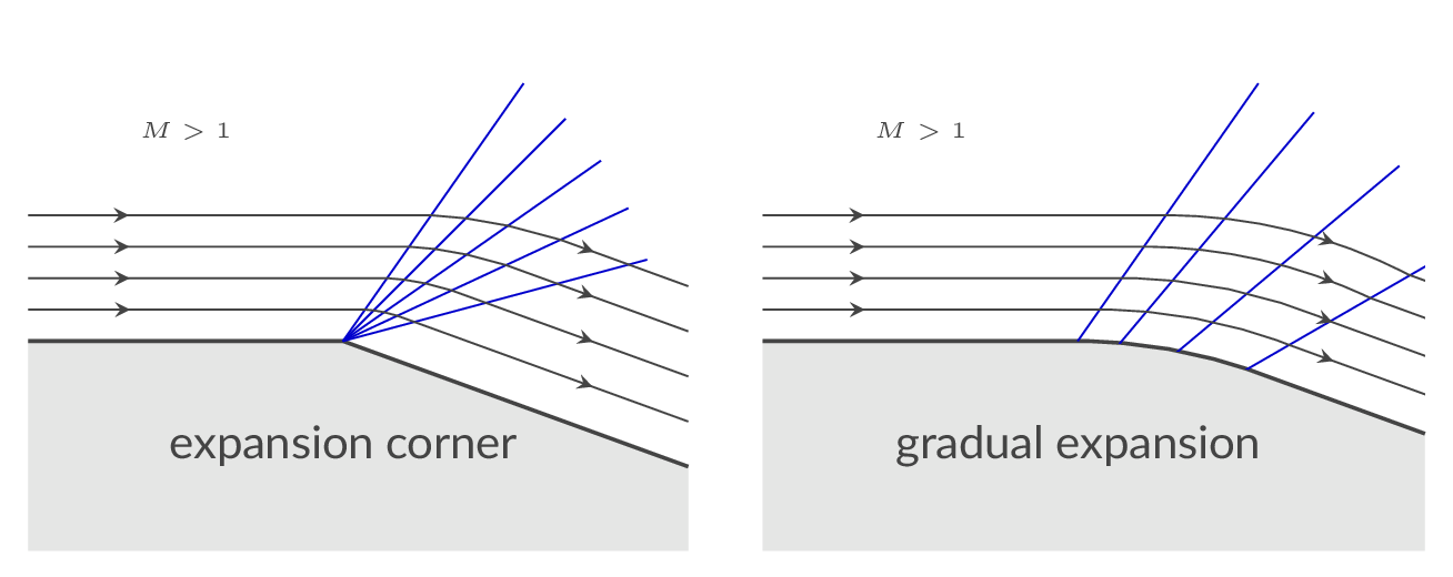
The expansion fan (Prandtl-Meyer expansion) generated at the expansion corner in the figure below will gradually change the flow direction and the end result is a net turning of the flow such that it follows the wall downstream of the corner.

The left and right ends of the expansion fan are defined by the angle of Mach waves in the upstream and downstream region, respectively.

The net turning may be calculated as follows:

where \(\nu(M)\) is the Prandtl-Meyer function evaluated at a position with Mach number \(M\)

| flow property | change over expansion region |
|---|---|
| density | decreases |
| pressure | decreases |
| temperature | decreases |
| velocity | increases |
| Mach number | increases |
More details can be found here:
| Oblique shocks and expansion waves | (Prandtl-Meyer expansion waves) |
Update gas data if needed. The default values are \(\gamma=1.4\) and \(R=287\), which corresponds to air. Changing the gas properties will affect all sections of the CFLOW calculator.
| ratio of specific heats \(\left(\gamma=C_p/C_v\right)\): | ||||
| gas constant \(\left(R\right)\): |
Evaluate the Prandtl-Meyer function for the specified Mach number.
| Mach number \(\left(M\right)\) |
Specify the upstream flow conditions and the expansion region net turning. Press recalculate to update the downstream flow conditions.
| upstream Mach number \(\left(M_1\right)\) | ||||||
| flow deflection angle \(\left(\theta\right)\) | ||||||
| upstream pressure \(\left(p_1\right)\) | ||||||
| upstream temperature \(\left(T_1\right)\) |
The convergent divergent nozzle is the only device we can use to generate a steady supersonic flow. This is easy to realize by examining the area-velocity relation.
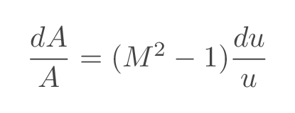
Using the quasi-one-dimensional approach all flow proerties varies in one direction only. the Mach number distribution in the flow direction is related to the cross-section area (shape) of the nozzle by the area-Mach-number relation

where \(A^*\) is the cross-section area at sonic conditions, which, as can be seen from the area-velocity relation above, will appear at the nozzle throat.
As the pressure ratio over the nozzle is increased by either increasing the total pressure at the inlet or decreasing the downstream static pressure, the massflow through the nozzle will increase as long as the flow in the throat section is subsonic. There are an infinite number of possible solutions with subsonic flow throughout the nozzle where the Mach number increases gradually through the convergent part of the nozzle and then decreases again in the diverging part of the nozzle.
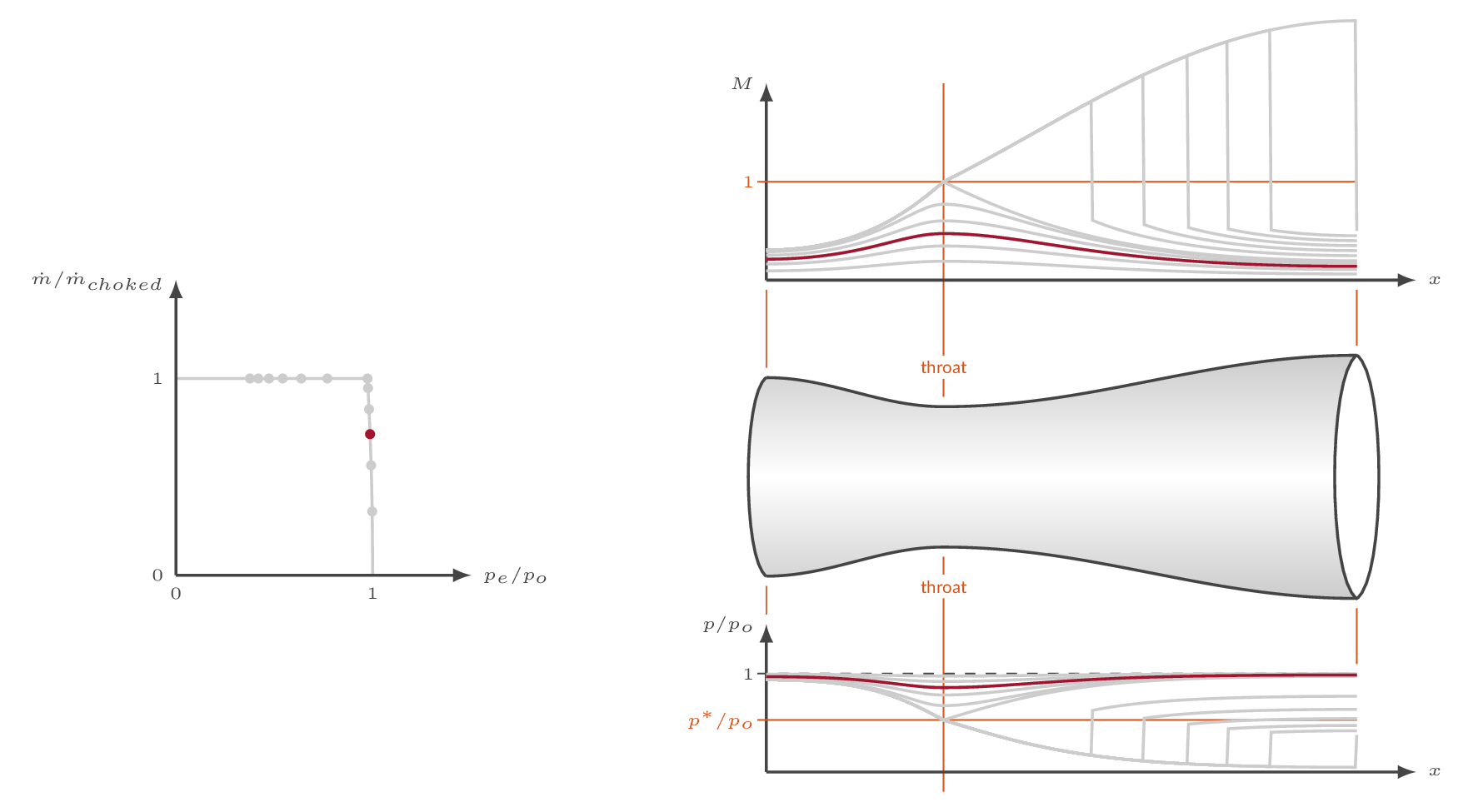
For a specific nozzle pressure ratio (the critical pressure ratio), the Mach number will become one in the throat section. For this pressure ratio the nozzle flow becomes choked which means that we have reached the maximum possible massflow through the nozzle. Increasing the pressure ratio will not affect the massflow.
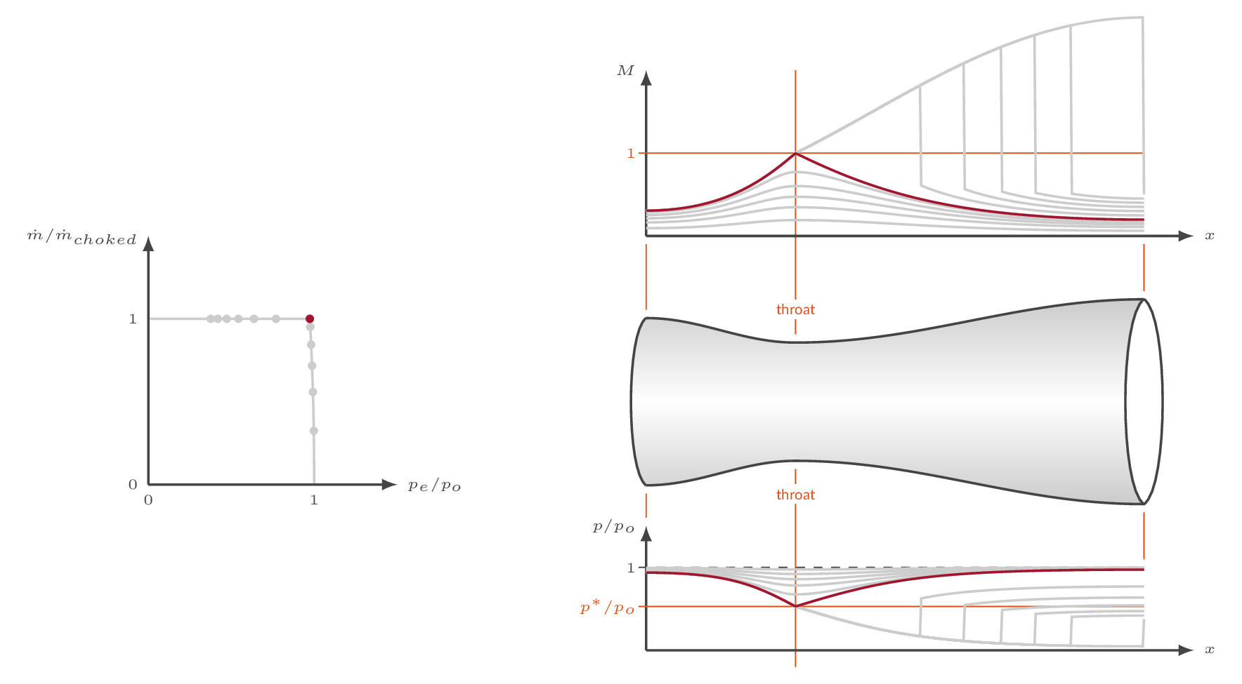
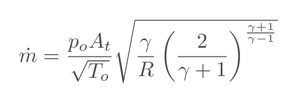
The maximum massflow through a specific nozzle and inlet conditions can be calculated using the following relation
Increasing the pressure ratio over the nozzle beyond the critical pressure ratio, the Mach number will increase in the diverging part of the nozzle following the supersonic solution of the area-Mach-number relation. In order to match the downstream static pressure, a normal shock will appear somewhere in the diverging part of the nozzle. The shock location is a function of nozzle shape and pressure ratio.
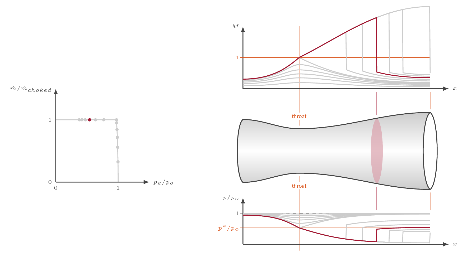
Note that \(A^*\) will change over the shock. \(A^*\) is a constant value both upstream of the shock and downstream of the shock but it is two different constants. Since the massflow is constant and total pressure is unaffected by the normal shock, it can be seen from the massflow relation above that the product \(p_oA^*\) is constant over the shock.
The location of the internal shock moves downstream as the pressure ratio is increased. The further downstream the shock appears, the stronger it is. Eventually, for a specific pressure ratio, the shock will be formed at the nozzle exit plane - shock-at-exit conditions.
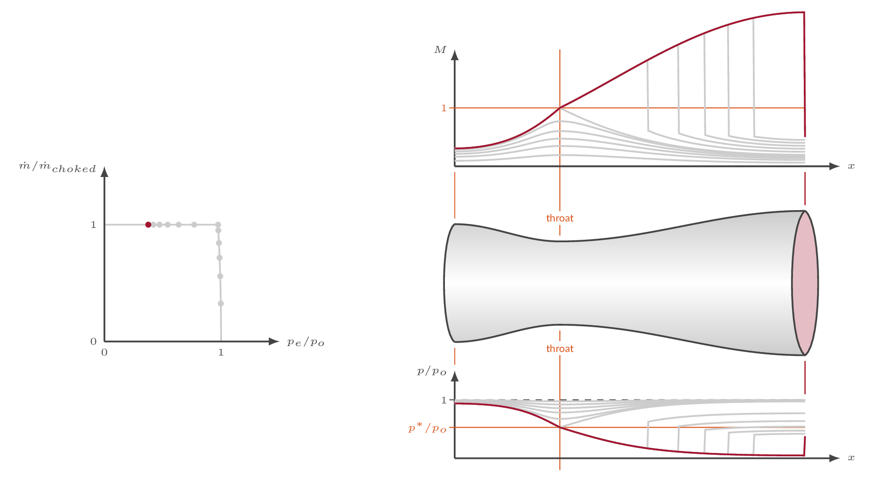
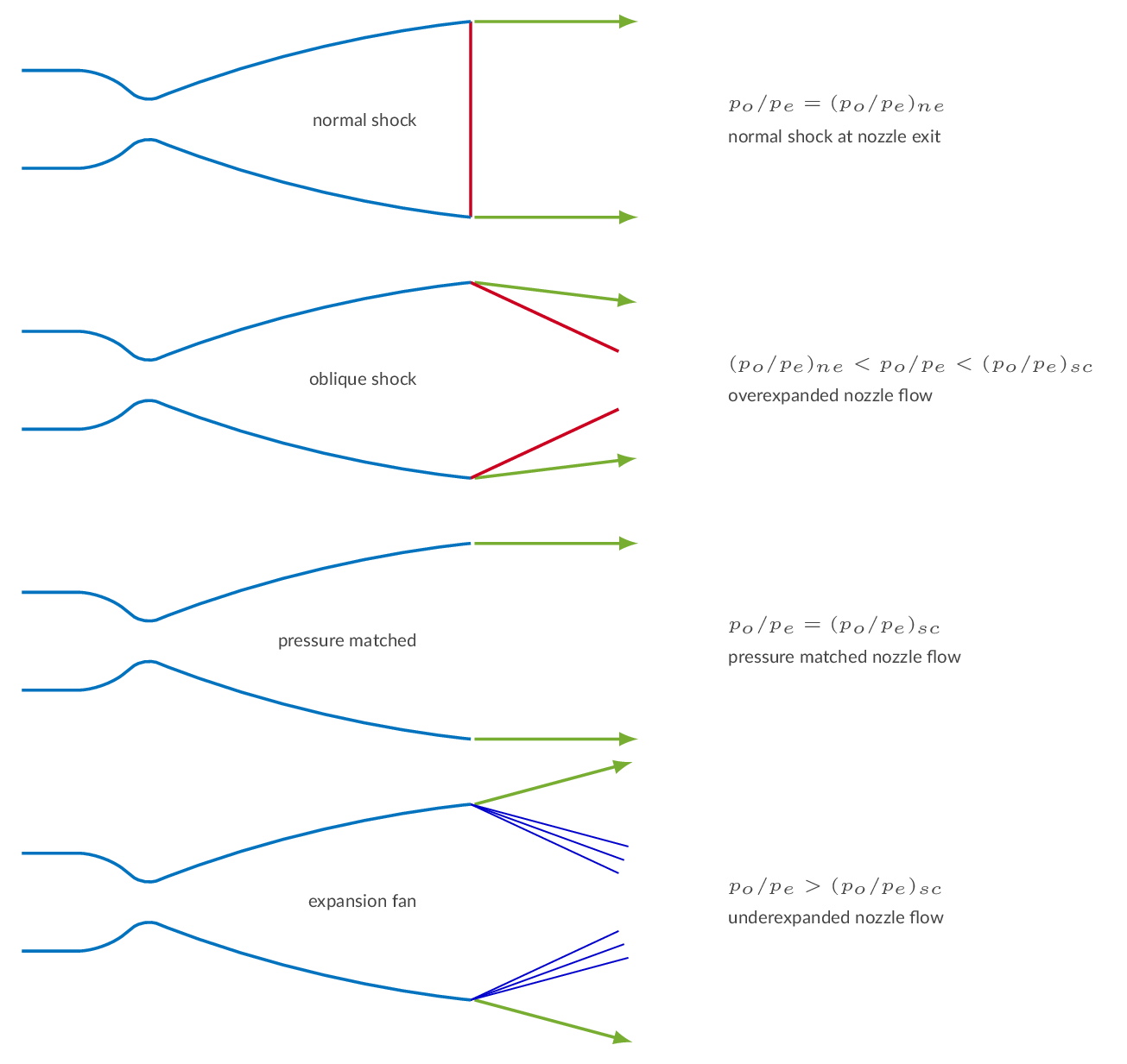
From the shock-at-exit condition and beyond, the internal nozzle flow is free of shocks. Increasing the pressure ratio further will generate an overexpanded nozzle flow where we will see oblique shocks formed downstream of the nozzle exit. There is a specific pressure ratio (supercritical) for which the pressure at the nozzle exit matches the downstream. For pressure ratios higher than the supercritical, the nozzle flow is underexpanded and expansion waves will form downstream of the nozzle exit.
More details can be found here:
| Quasi-one-dimensional flow | (Area-velocity relation & Nozzles) |
Update gas data if needed. The default values are \(\gamma=1.4\) and \(R=287\), which corresponds to air. Changing the gas properties will affect all sections of the CFLOW calculator.
| ratio of specific heats \(\left(\gamma=C_p/C_v\right)\): | ||||
| gas constant \(\left(R\right)\): |
Evaluate the area-Mach-number relation based on the specified input.
| Select problem type | ||||||
| Mach number \(\left(M\right)\) | ||||||
| area ratio \(\left(A/A^*\right)\) | ||||||
Specify total temperature and total pressure at the nozzle inlet and the nozzle throat and exit areas. Nozzle pressure ratios for choked flow, shock-at-exit conditions and supercritical flow are calculated.
| throat area: | ||||||
| exit area: | ||||||
| plenum pressure \(\left(p_o\right)\): | ||||||
| plenum temperature \(\left(T_o\right)\): | ||||||
| downstream pressure \(\left(p_b\right)\): |
The tables below presents nozzle characteristics generated based on the specified nozzle area ratio.
The tables below presents nozzle data for relevant flow stations generated based on the specified nozzle area ratio and nozzle pressure ratio. The nozzle flow is categorized as:
A so-called minimum-length nozzle is designed using Method of Characteristics. A minimum-length nozzle does not have a smooth expansion section downstream of the nozzle throat. If the length of the expansion section is shrunk down to zero, an expansion fan will be generated at the throat "corner". A small complex expansion region with interaction of left-running and right-running expansion waves, will form downstream of the throat.
Specify nozzle exit Mach number (greater than 1.0) and number of characteristics to be used (greater than 2). Press recalculate to generate a nozzle contour.
| nozzle exit Mach number: | ||||||
| number of characteristics: | ||||||
| nozzle throat height: | (default value: 2.0 m) | |||||
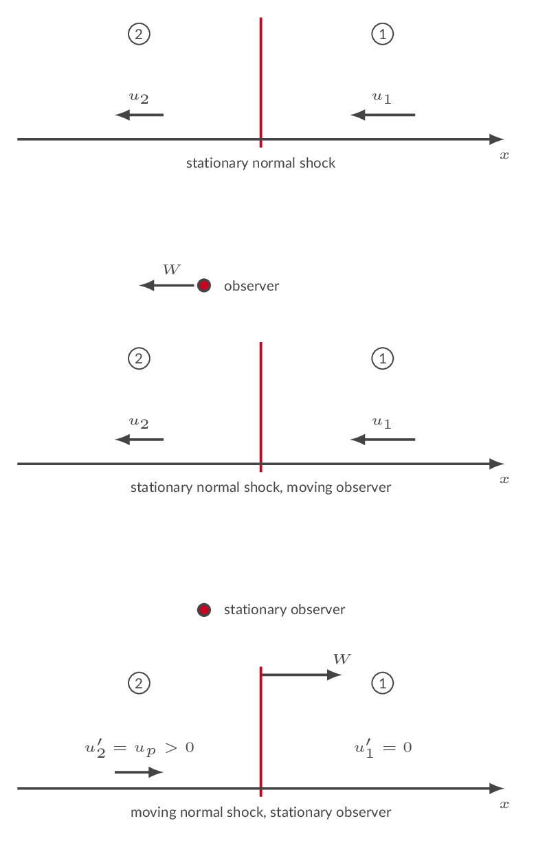
The figure below depicts three scenarios of one-dimensional flow with a normal shock. The upper figure shows a stationary normal shock. In the next figure, a moving observer has been introduced. The observer moves to the left with the constant velocity \(W\), which means that the observer is in an inertial system and physical laws are unchanged. The observer sees a shock moving to the right with the velocity \(W\). From the frame of reference of the observer, the gas velocity ahead of the shock is \(u_1'=W-u_1\) and the gas velocity behind the shock is \(u_2'=W-u_2\). I the lower picture, the observer is stationary, and the shock is moving to the right with the constant velocity \(W\). The conclusion here is that if the shock is moving with a constant velocity one can use the governing equations for normal shocks with gas velocities specified in the frame of reference of the moving shock.
With the governing equations established as described above one can derive a relation between the shock pressure ratio and the Mach number of the moving shock.


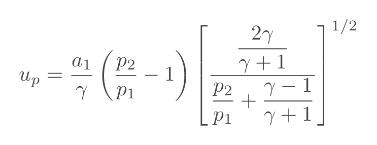
The velocity of the induced flow behind the moving shock can be obtained using the following relation
When the incident shock reaches a wall, a reflected shock wave will be generated such that the induced velocity is canceled. The Mach number of the reflected shock wave is calculated as

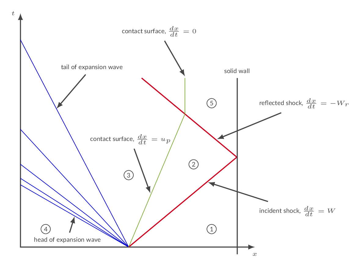
The figure below depicts an incident shock reflected at a wall and the corresponding reflected shock. The incident shock moves into a stagnant fluid (region 1). The fluid behind the shock will move in the direction of the shock with the induced velocity \(u_p\) (regions 2 and 3). The velocity of the fluid behind the reflected shock will be zero by definition (region 5). The green line is a contact surface, which is a discontinuity separating the fluid that has been passed by the incident shock and the fluid that has been passed by the expansion. In the shock tube, the contact surface constitutes an interface between the driver section gas and the driven section gas. The fluid on both sides of the contact surface must have the same velocity, \(u_p\), and pressure. There will, however, be a discontinuity in Entropy, Temperature and density over the contact surface, i.e., between region 2 and region 3. The blue lines in the left end of the figure represents an expansion wave moving to the left. The head of the expansion wave moves into stagnant fluid in region 4.
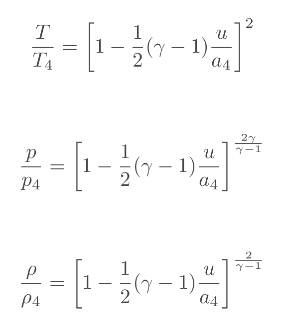
Flow properties at a location witin the expansion wave can be calculated using the following relations
More details can be found here:
Update gas data if needed. The default values are \(\gamma=1.4\) and \(R=287\), which corresponds to air. Changing the gas properties will affect all sections of the CFLOW calculator.
| ratio of specific heats \(\left(\gamma=C_p/C_v\right)\): | ||||
| gas constant \(\left(R\right)\): |
Select problem type and specify data accordingly. Specify temperature and pressure ahead of the moving shock (region 1). Moving shock data will be calculated based on the specified input and presented in the table below.
| Select problem type | ||||||
| pressure ratio \(\left(p_2/p_1\right)\) | ||||||
| incident shock Mach number \(\left(M_s\right)\) | ||||||
| induced velocity \(\left(u_p\right)\) | ||||||
| reflected shock Mach number \(\left(M_r\right)\) | ||||||
| temperature ratio \(\left(T_5/T_1\right)\) | ||||||
| pressure ratio \(\left(p_5/p_1\right)\) | ||||||
| pressure ahead of shock wave \(\left(p_1\right)\) | ||||||
| temperature ahead of shock wave \(\left(T_1\right)\) | ||||||
Select problem type and specify data accordingly. Specify temperature and pressure ahead of the moving expansion wave (region 4). Expansion wave data will be calculated based on the specified input and presented in the table below.
| Select problem type | ||||||
| velocity \(\left(u\right)\) | ||||||
| temperature ratio \(\left(T/T_4\right)\) | ||||||
| pressure ratio \(\left(p/p_4\right)\) | ||||||
| expansion wave head pressure \(\left(p_4\right)\) | ||||||
| expansion wave head temperature \(\left(T_4\right)\) | ||||||
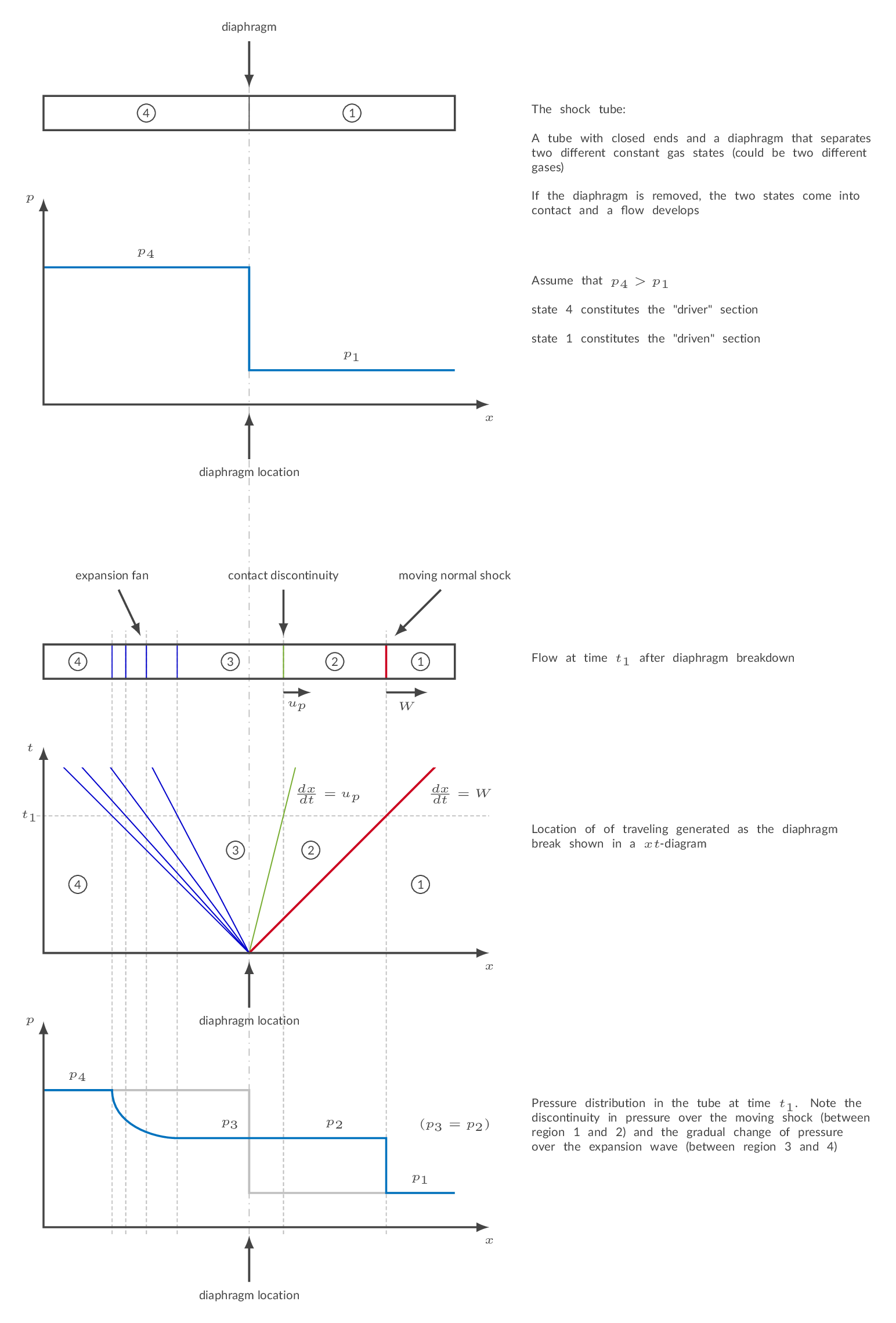
The shock tube is a classic application of unsteady waves in compressible flow. The figure below describes the shock tube setup setup schematically.
The figure below depicts three scenarios of one-dimensional flow with a normal shock. The upper figure shows a stationary normal shock. In the next figure, a moving observer has been introduced. The observer moves to the left with the constant velocity \(W\), which means that the observer is in an inertial system and physical laws are unchanged. The observer sees a shock moving to the right with the velocity \(W\). From the frame of reference of the observer, the gas velocity ahead of the shock is \(u_1'=W-u_1\) and the gas velocity behind the shock is \(u_2'=W-u_2\). I the lower picture, the observer is stationary, and the shock is moving to the right with the constant velocity \(W\). The conclusion here is that if the shock is moving with a constant velocity one can use the governing equations for normal shocks with gas velocities specified in the frame of reference of the moving shock.

With the governing equations established as described above one can derive a relation between the shock pressure ratio and the Mach number of the moving shock.


The velocity of the induced flow behind the moving shock can be obtained using the following relation

When the incident shock reaches a wall, a reflected shock wave will be generated such that the induced velocity is canceled. The Mach number of the reflected shock wave is calculated as

The figure below depicts an incident shock reflected at a wall and the corresponding reflected shock. The incident shock moves into a stagnant fluid (region 1). The fluid behind the shock will move in the direction of the shock with the induced velocity \(u_p\) (regions 2 and 3). The velocity of the fluid behind the reflected shock will be zero by definition (region 5). The green line is a contact surface, which is a discontinuity separating the fluid that has been passed by the incident shock and the fluid that has been passed by the expansion. In the shock tube, the contact surface constitutes an interface between the driver section gas and the driven section gas. The fluid on both sides of the contact surface must have the same velocity, \(u_p\), and pressure. There will, however, be a discontinuity in Entropy, Temperature and density over the contact surface, i.e., between region 2 and region 3. The blue lines in the left end of the figure represents an expansion wave moving to the left. The head of the expansion wave moves into stagnant fluid in region 4.

Flow properties at a location witin the expansion wave can be calculated using the following relations

From the relations above, a shock-tube relation may be derived where the pressure ratio over the incident shock is an implicit function of the pressure ratio over the diaphragm.

More details can be found here:
Specify driven section gas properties \((\gamma_1,\ R_1)\) and driver section gas properties \((\gamma_4,\ R_4)\).
| ratio of specific heats (driven section, \(\gamma_1\)): | ||||
| gas constant (driven section, \(R_1\)): |
| ratio of specific heats (driver section, \(\gamma_4\)): | ||||
| gas constant (driver section, \(R_4\)): |
Specify length of the driven section and the driver section.
| driver section tube length \(\left(L_4\right)\) | ||||
| driven section tube length \(\left(L_1\right)\) |
Select problem type and specify input accordingly. Press recalculate to update shock tube data based on the specified input. The calculated data is presented in the table and figures below. The tables show velocities and Mach numbers of traveling waves and flow field properties in regions 1-5. The lower figure shows a schematic representation of the traveling waves in the shock tube in the form of a xt-diagram.
| Select problem type | ||
| (driven section initial conditions and driver section initial temerature needed for all problem types) | ||
| driven section pressure \(\left(p_1\right)\) | ||||||
| driven section temperature \(\left(T_1\right)\) | ||||||
| driver section pressure \(\left(p_4\right)\) | ||||||
| driver section temperature \(\left(T_4\right)\) | ||||||
| incident shock Mach number \(\left(M_s\right)\) | ||||||
| reflected shock Mach number \(\left(M_r\right)\) | ||||||
| induced velocity \(\left(u_p\right)\) | ||||||
| region 5 temperature \(\left(T_5\right)\) | ||||||
| region 5 pressure \(\left(p_5\right)\) | ||||||
| shock pressure ratio \(\left(p_2/p_1\right)\) |
